Permanent magnet rotor e1655961736623.jpeg.
Jan 10, 2022 · The rated power and speed of the permanent magnet grinding electric spindle are 7.5Kw and 950r/min, respectively.The main parameters of the PMGES are as follows, the rotor mass is m = 5.66 kg; the rotor radius is R = 0.072 mm; the axial length of the air gap is L = 0.178 mm, nominal air gap length is δ 0 = 3 × 10 −3 m, air permeability is ...
This paper is focused on the optimal design, simulation, and experimental testing of a counter-rotating double-rotor axial flux permanent magnet synchronous generator (CRDR-AFPMSG) for wind turbine applications. For the optimal design of the CRDR-AFPMSG, the particle swarm optimization algorithm to maximize efficiency and …This paper is focused on the optimal design, simulation, and experimental testing of a counter-rotating double-rotor axial flux permanent magnet synchronous …Structure Review of Inner Permanent Magnet Synchronous machines (PMSM) Radial magnetization pattern can used applied to the permanent magnet motors, motors are in different size and shapes for the different applications. In this section different kind of PM motors will be reviewed. Field Excitation (FE) Permanent Magnet (PM) …In this paper, a novel dual mechanical port dual rotor counter-rotating permanent magnet flux switching generator (DMPDRCR-PMFSG) for wind turbine applications is proposed. Power distribution between the inner and outer rotors of the proposed DMPDRCR-PMFSG that contributes to the cumulative output power is …Abstract: For the high-frequency permanent magnet electrical machine, a reasonable mechanical aspect design is crucial to meet its stability and reliability. This study focuses on the accurate modelling and analysis of the natural frequencies and modes of the rotor assembly for a designed and manufactured 100 kW 32,000 r/min motor.
The SPMSM has the permanent magnets fixed on the surface of the rotor leading to a symmetrical radial air-gap reluctance path between the rotor and the stator core. The IPMSM has the permanent magnets inserted inside the rotor core leading to a non-symmetrical radial air-gap reluctance path between the rotor and the stator core. Non−Magnetic Rotor Core Rotor Magnets Rotor Pole Pieces Figure 2: Axial View of a Flux Concentrating Motor The geometry of one type of internal magnet motor is shown (crudely) in Figure 2. The permanent magnets are oriented so that their magnetizationis azimuthal. They are located between wedges of magnetic material (the pole pieces) in …Jun 23, 2022 · The rotor overtemperature caused by losses is one of the important issues for the high-speed electrical machine. This paper focuses on the rotor loss analysis and CFD-thermal coupling evaluation for 105 kW, 36,000 r/min HSPMSM. Three types of sleeve materials as carbon-fiber, Titanium alloy, and stainless steel are introduced in this paper, researching the effects of sleeve conductivity ...
For permanent-magnet (PM) machines, only specific stator MMF harmonic, known as working harmonic, interacts with the PM field to produce continuous electromagnetic torque . Lower and higher order stator MMF spatial harmonics rotating at different speeds to the rotor, will bring about unwelcome effects, such as eddy current …
2.1 Selection of Solution Variants for Analysis. In this study, an analysis of the selection of the number of stator slots to the number of magnetic poles was carried out for the structure of the Permanent Magnet Synchronous Motor (PMSM) with an external rotor, with surface mounted magnets (SPM) with a double-layer, concentrated winding …2.1 Design of Rotor Eccentric Arc and Performance Analysis. This paper takes a permanent-magnet rotor as an example. Figure 1 shows 1/8 models of a rotor without an eccentric arc design, a rotor core designed with a conventional eccentric arc, and a rotor core designed with the improved eccentric arc. The permanent magnets of the …This control method can control the AC permanent magnet servo motor as a DC permanent magnet motor in a sense. According to Equations (1)–(3), the second-order dynamic equation of the position ring of the PMSM is expressed as follows: (4) { θ ˙ = ω ω ˙ = b i q + d (4) where b = 1.5 p n ψ f / J is a disturbance composed of unknown friction …External rotors of “outrunner” type. Rotors with additional bandage (Polyglas, Kevlar, carbon) Rotors with protecting sleeve. Contact us. Jan Kratochvil ml. +420 607 570 823 …Abstract: For the high-frequency permanent magnet electrical machine, a reasonable mechanical aspect design is crucial to meet its stability and reliability. This study focuses on the accurate modelling and analysis of the natural frequencies and modes of the rotor assembly for a designed and manufactured 100 kW 32,000 r/min motor.
Jan 31, 2017 · Understanding permanent magnet motors. A permanent magnet (PM) motor is an ac motor that uses magnets imbedded into or attached to the surface of the motor’s rotor. This article provides an elementary understanding behind the terminology, concepts, theory, and physics behind PM motors.
The advantages of choosing Sintex® magnetic rotors are as follows: Patented solutions. Complete solutions. 100% sealed enclosure – can run as wet runner. Corrosion-resistant materials. High efficiency / low energy loss. Maintenance-free. Long service life. …
Jun 23, 2022 · The rotor overtemperature caused by losses is one of the important issues for the high-speed electrical machine. This paper focuses on the rotor loss analysis and CFD-thermal coupling evaluation for 105 kW, 36,000 r/min HSPMSM. Three types of sleeve materials as carbon-fiber, Titanium alloy, and stainless steel are introduced in this paper, researching the effects of sleeve conductivity ... Dual Rotor Axial Flux Generator (DRAFG) is a permanent magnet axial flux generator commonly used for low speed power generation using wind power. This generator can generate useful amount of ...Non−Magnetic Rotor Core Rotor Magnets Rotor Pole Pieces Figure 2: Axial View of a Flux Concentrating Motor The geometry of one type of internal magnet motor is shown (crudely) in Figure 2. The permanent magnets are oriented so that their magnetizationis azimuthal. They are located between wedges of magnetic material (the pole pieces) in …In this study, we performed an electromagnetic characteristic analysis of a permanent magnet synchronous machine considering the current waveform based on static rotor eccentricity. First, the characteristics of the back electromotive force were analyzed through the no-load analysis of the analysis model according to static rotor …Axial-flux permanent magnet (AFPM) motors have been attracting great interest due to their key advantages of high-torque density and compact structure. Concentrated windings are commonly used for AFPM motors since they significantly reduce the radial length of the end windings. This paper proposes a novel double-sided stator …Abstract. Interior permanent magnet synchronous machines (IPMSMs) with V-shaped permanent magnet (PM) rotors are widely …
To enable a successful transition, the availability of resources must be ensured. In particular, rare earth materials used in permanent magnets of permanent magnet synchronous machines (PMSM) are already considered as a critical resource. Therefore, high performance magnets of existing PMSM rotors must be recovered and …To solve the problem of tension stress caused by centrifugal force and caused by high-speed operation of permanent magnet (PM) rotor, a FeCo-based PM rotor structure model is proposed. Based on …A 1 kW, 510 rpm, 24-slots and 8-pole inner runner type surface permanent magnet mounted radial flux brushless DC motor with seven different permanent magnet pole shape rotor is investigated.An interior permanent magnet synchronous motor (IPMSM) with ‘VV—’ shape rotor topology structure is proposed. The established two-dimensional (2D) parameterized finite element analysis (FEA) models are used to analyze and compare the output average torque, torque density, air-gap flux density and back electromotive force …The actual power capacity of permanent magnet synchronous machine for electric vehicles is usually limited by rotor temperature, ... Usually, measuring the temperature of the rotor permanent magnet is very difficult by equipping sensors to rotate the body directly. Some common techniques include slip rings, ...The most obvious performance difference is that a PMAC motor rotates at the same speed as the magnetic field produced by the stator windings, meaning it is a synchronous machine. If the field is “rotating” at 1800 rpm, the rotor turns at the same speed. An induction motor, on the other hand, is considered an asynchronous machine.
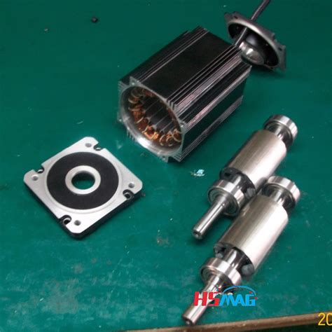
Permanent Magnet Rotors. Magnetic motor rotor, which is formed by magnetic steel, metal shaft or metal shell. According to detailed application situation, the …
To solve the problem of tension stress caused by centrifugal force and caused by high-speed operation of permanent magnet (PM) rotor, a FeCo-based PM rotor structure model is proposed. Based on …An interior permanent magnet synchronous motor (IPMSM) with ‘VV—’ shape rotor topology structure is proposed. The established two-dimensional (2D) parameterized finite element analysis (FEA) models are used to analyze and compare the output average torque, torque density, air-gap flux density and back electromotive force …The windings of coreless axial flux permanent-magnet machine (CAFPM) are exposed to the rotor magnetic field, where each back electromotive force (EMF) harmonic is induced not only by several ...Permanent Magnet (PM) Brushless Direct Current (BLDC) actuators/motors have many advantages over conventional machines, including high efficiency, easy controllability over a wide range of operating speeds, etc. There are many prototypes for such motors; some of them have a very complicated construction, and this ensures their …An interior permanent magnet synchronous motor (IPMSM) with ‘VV—’ shape rotor topology structure is proposed. The established two-dimensional (2D) parameterized finite element analysis (FEA) models are used to analyze and compare the output average torque, torque density, air-gap flux density and back electromotive force …1 Introduction. Flux-switching permanent-magnet (FSPM) motors have advantages such as high-power and -torque density, high efficiency and simple and robust mechanical structure in the rotor [1-4].These motors have bipolar flux linkage and sinusoidal back-electromotive force (EMF) [].In FSPM motors, because of the placement of …Among them, the NS type rotor has a structure in which the permanent magnetization direction of the two-sided rotor is opposite. One rotor permanent magnet magnetic flux flow to the opposite rotor. The advantage is that there is no magnetic flux flowing through the Stator back-yoke, making the design easier. Furthermore, by …Abstract--Multi-phase permanent magnet assisted synchronous reluctance motor (PMa-SynRM) is proposed as one of the optimal machine designs for vehicular applications such as electric vehicles (EVs) due to their fault tolerant operation capability. However, optimization of the multi-phase PMa-SynRMs for in-wheel applications in EVs and aircrafts ... The accurate calculation and reduction of electromagnetic force waves are important prerequisite for the evaluation and optimization of electromagnetic vibration. In this paper, an accurate calculation method of air gap permeance is proposed, the air gap flux density and the resulting electromagnetic force waves of 6p36s surface-mounted …
2.2 External rotor permanent magnet motor rotor air gap magnetic field When the motor is running at no load, the air gap magnetic field is provided by the permanent magnet alone. The generated magnetic field rotates together with the rotor and the rotational speed is synchronous speed.
Permanent-Magnet Motors Wen L. Soong, Member, IEEE, and Nesimi Ertugrul, Member, IEEE Abstract— This paper compares the field-weakening perfor-mance under rated and overload conditions of synchronous reluctance and interior permanent-magnet motors against that of a baseline 2.2-kW induction machine. Four prototype rotors based
Jan 31, 2017 · Understanding permanent magnet motors. A permanent magnet (PM) motor is an ac motor that uses magnets imbedded into or attached to the surface of the motor’s rotor. This article provides an elementary understanding behind the terminology, concepts, theory, and physics behind PM motors. Permanent Magnet Rotors High-Speed, High-Reliability, High-Efficiency Permanent Magnet Rotors For over 25 years, Integrated Magnetics has developed and refined the …1,417 permanent magnets stock photos, 3D objects, vectors, and illustrations are available royalty-free. See permanent magnets stock video clips. Experimental electric generator on white background, consists of copper coils and magnets. A generator is a device that converts mechanical energy to electrical energy for use in an external circuit.A high-speed (HS) permanent magnet (PM) synchronous motor (HSPMSM) with a carbon fiber-reinforced plastic (CFRP) protective sleeve in the surface-mounted rotor was explored in this study.To solve the problem of tension stress caused by centrifugal force and caused by high-speed operation of permanent magnet (PM) rotor, a FeCo-based PM rotor structure model is proposed. Based on …This paper presents a design method of the basic model of high-speed surface-mounted permanent magnet synchronous motor (SPMSM) comprehensively considering the mechanical and electromagnetic properties based on the subdomain method. In the rotor design stage, the mechanical stresses of the permanent magnet …Synchronous motor. Miniature synchronous motor used in analog clocks. The rotor is made of permanent magnet. Small synchronous motor with integral stepdown gear from a microwave oven. A synchronous electric motor is an AC electric motor in which, at steady state, [1] the rotation of the shaft is synchronized with the frequency of the supply ...Aiming at the rotor strength problem of high speed permanent magnet synchronous motor (HSPMSM), a design method for maximum outer diameter of permanent magnet is proposed. Firstly, on the basis of mechanics of materials, the stress analytical model of HSPMSM rotor with anisotropic material is established. Then, the …Dec 1, 2017 · In their work, a range of electric machine options are considered and it is concluded that a synchronous machine with a permanent magnet (PM) rotor will be the most efficient and power dense. In addition to applications in turbocharging, Gerada [ 3 ] highlight an increasing demand for high-speed electrical machines in flywheel energy storage ... Rmr reluctance of the magnet to rotor back iron leakage flux Rmm reluctance of the magnet to magnet leakage flux Rg reluctance of the airgap rb mean radius of stator winding, i.e. (ri + ro)/2 ri inner radius of magnet ro outer radius of magnet Sc area of one conductor cross-section Sp arc length of one coil pitch at the outer radius ro of the ...Permanent magnet traction motor has the advantages of high efficiency, high power density, high torque density and quick dynamic response, which has been widely used in the traction field of electric vehicle. The high-performance control of permanent magnet traction motor depends on accurate rotor position information, which is usually …Aug 1, 2022 · The axial lengths of the IPM rotor and the SynRM rotor are respectively changed by changing the parameters L and H. It shows that when the width of the permanent magnet L is 85 mm and the thickness H is 4 mm, the maximum total torque reaches 174.2 N m. The length of the permanent magnet rotor is 141.17 mm. Download : Download high-res image (177KB)
Since the pole arc coefficient of the rotor permanent magnet is 0.5, according to Ref. 28, the magnetomotive force generated by the permanent magnet is equal to that generated by the adjacent FMP.Structure Review of Inner Permanent Magnet Synchronous machines (PMSM) Radial magnetization pattern can used applied to the permanent magnet motors, motors are in different size and shapes for the different applications. In this section different kind of PM motors will be reviewed. Field Excitation (FE) Permanent Magnet (PM) …This study proposes design procedures for the permanent-magnet-biased magnetic bearings (PEMBs) in rotor systems. Many aspects of designing magnetic …Since the teeth of the stator and the magnetic bridge of the rotor are prone to magnetic saturation, the grids in these places are encrypted, as shown in Figure 2. The specific mesh settings are as follows: stator teeth 0.2 mm, stator yoke 2 mm, rotor edge 0.2 mm, rotor yoke 2 mm, and permanent magnet 2 mm.Instagram:https://instagram. cojiendo con micunadajerseysstevens 22 410 over under pricewho put harry Jan 13, 2023 · Structure Review of Inner Permanent Magnet Synchronous machines (PMSM) Radial magnetization pattern can used applied to the permanent magnet motors, motors are in different size and shapes for the different applications. In this section different kind of PM motors will be reviewed. Field Excitation (FE) Permanent Magnet (PM) Hybrid Excitation (HE) student exploration nuclear decayfilmulete xxl Understanding permanent magnet motors. A permanent magnet (PM) motor is an ac motor that uses magnets imbedded into or …It should be understood that the “rotor inside” vs. “rotor outside” distinction is in fact trivial, with very few exceptions, which we will note. 2.1 Surface Magnet Machines Figure 1 shows the basic magnetic morphology of the motor with magnets mounted on the surface of the rotor and an otherwise conventional stator winding. stra A high-speed (HS) permanent magnet (PM) synchronous motor (HSPMSM) with a carbon fiber-reinforced plastic (CFRP) protective sleeve in the surface-mounted rotor was explored in this study.A high-speed (HS) permanent magnet (PM) synchronous motor (HSPMSM) with a carbon fiber-reinforced plastic (CFRP) protective sleeve in the surface-mounted rotor was explored in this study.Sep 2, 2020 · In the PMSG that has not been the CT reduction technique, the rotor permanent magnets (PMs) have an increasing effect on the CT since each PM has the same relative position with reference to the stator slots . The CT in each PM is in the same phase as the others, so, the harmonic component of each is added together then, CT has become higher.